Note: this article is several years old, and information contained may no longer be accurate
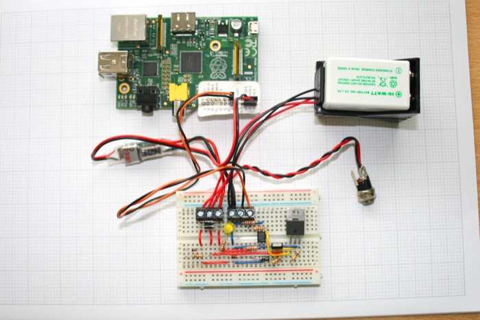
This is a step by step instructions on how to make a battery backup circuit for your Raspberry Pi computer. For more information about Raspberry Pi visit the Foundation's website.
UPDATE: A better solution now exists https://pi.gate.ac.uk/pages/mopi.html
First I'd like to explain a little bit about what I tried to achieve with this design and also pros and cons of this approach. I'm using my Raspberry Pi as a backup device with two hard drives connected to it, to back up various online servers that I administer. I use automated backup scripts based on Rsnapshot, and also I'm using this particular Pi as an Apple time machine server. Because Raspberry Pi is a very low power device, I thought it would be possible to design a cheap backup power supply using a 9V rechargeable battery, and this way prevent any abrupt shutdowns during power cuts or when someone accidentally unplugs it from the mains. As an added feature it also will provide a convenient way to safely power the device off without adding a hardware button or logging-in remotely and issuing a shutdown. But what this circuit doesn't currently do is monitor battery levels, nor provide any king of low voltage cut off, but there is a time limit/delay after which it will automatically power off and disconnect the battery.
Precautions: Triple check all connections to and from Raspberry Pi before connecting either power supply or battery as I have made a mistake and applied 9V to the GPIO pins which destroyed it instantly. Even better is to use a buffer board of some kind, there are plenty sold online. Also double check that the power supply delivers expected voltage before connecting it to the circuit, and don't use bad quality power supplies. DO NOT work with mains voltage unless you are qualified.
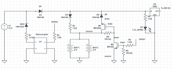
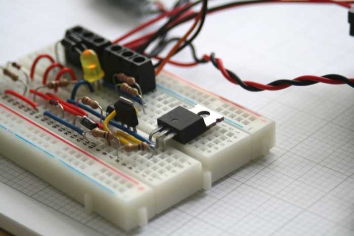
The Circuit
- Trickle charge the battery while on mains power
- Send a signal to Pi GPIO pin when mains power is disconnected
- issue a shutdown after a few minutes if power haven't returned (Done via software)
- disconnect the battery from the circuit after shutdown is completed (this is to prevent discharging the battery below its limit)
- keep a log file with all the time stamps and alerts for mains power, shutdowns and restarts of the Pi
My choice of battery being 9V initially was sufficient, but later I have realised that to power a usb hard drive via an on board USB ports required 2x 9V rechargeable batteries, as they are able to deliver up to 1.2 amps of peak current at 9V. Its important to highlight that you need Rechargeable batteries because normal ones cannot deliver so much current at once. You may be able to power Pi model B or A on its own, just, with a single 9V alkaline (may be sufficient for testing)
Why couldn't I simply use a standard 5V usb power supply you may ask? Because that would require a more complex pulse charger to multiply the voltage for charging 9V battery, but also the 5V supply I have (2A supply) struggled to keep the voltage above 4.5 volts when 2 hard drives were connected. So I went with a 2A 12 volt supply, which then is able to charge the battery via a resistor and also power an additional step down UBEC circuit which supplies a stable 5V to Pi
Key components
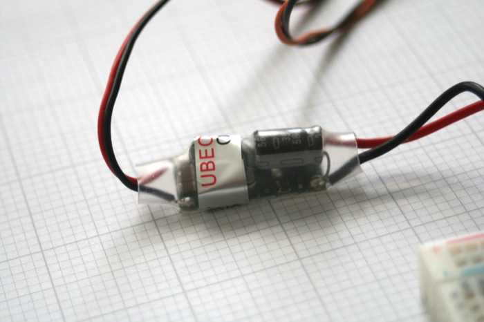
Voltage regulator either a linear 2-3 Amp one with a huge heat sink or a step down one, like this UBEC that has a 95% efficency. It can be purchased here, or much more cheaply here (but delivery takes few weeks)
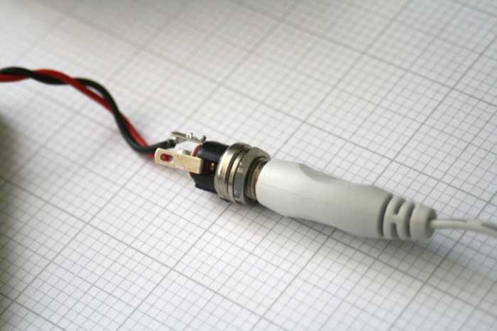
12V power supply I recommend at least 2Amp supply, which would match up nicely to the 3Amp voltage convertor and allow for power-hungry hard drives.
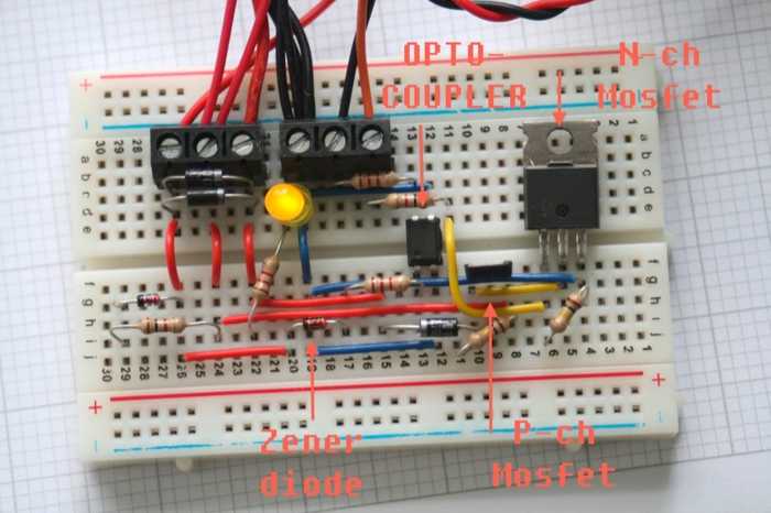
Power MOSFETs. they are required to be able to cut off power after a certain amount of time. The P-Channel MOSFET i've used was IRFU5305 P-channel Hexfet Power MOSFET. The second N-channel MOSFET is best to be a "logic-level" one which would guarantee it being turned on with Pi's GPIO pin. I've used an IRF510 which isn't a logic-level but it seems to work.
Optocoupler I didn't know how to safely detect that 12V power supply is off (Your suggestions would be welcome), and I had a spare FOD852 photo-darlington which I connected through a 5.1 V zener diode and a resistor, to make sure that it received a small voltage and current. I probably should have used a voltage divider using a zener, most important is to test the voltage because anything over 5V will destroy it instantly.
Rectifier diodes make sure those are rated at 2 amps, or use 2x 1A ones together.
R3 charging resistor This resistor is critical to make sure the correct amount of current flows into the battery(s). The rule of thumb for NiMh for trickle/constant charging is to put 1/40 to 1/100 of battery capacity. So for 200 mAh battery 5mA current is safe. Adjust this for your particular battery, if in doubt go for higher value resistor, and measure with you DMM.
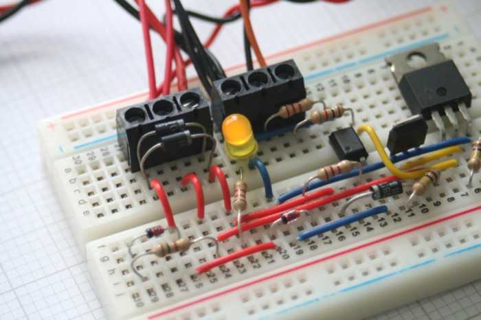

If you are able to solder this circuit together on a perforated board instead of the breadboard, then It's probably possible to fit it inside of the standard Raspberry Pi enclosures, with battery holders mounted on the outside, which would be quite neat for a finished item.
Programming Raspberry Pi
This section talks about the code side of the battery backup. Everything is pretty simple and should work either on Raspbian or Arch Linux (which i've used). There are 2 scripts whiten in python3, a startup script that initialises gpio 7 and a power monitoring script that runs constantly in the background.
Installing Python GPIO
I don't think this is required to do in Raspbian, as I think it's pre installed. But in Arch linux I've had to do something like the following (on the command line):
$ pacman -S python python-pip base-devel
$ pip install RPi.GPIO</pre>

          <h2>Startup script</h2>
          <p><code>gpio_start.py</code></p>
          <pre>#!/usr/bin/python

import time
import RPi.GPIO as GPIO

# using GPIO numbering
GPIO.setmode(GPIO.BCM)

#set up logging
import logging
logger = logging.getLogger('power')
hdlr = logging.FileHandler('/home/backup/power.log')
formatter = logging.Formatter('%(asctime)s %(levelname)s %(message)s')
hdlr.setFormatter(formatter)
logger.addHandler(hdlr)
logger.setLevel(logging.INFO)

#setting up power supply pin for battery backup
GPIO.setup(7, GPIO.OUT)
GPIO.output(7, True)

time.sleep(60)
logger.info('Started the system successfully (Power GPIO activated 60 seconds ago)')
This script starts via systemd in Arch linux or init.d in Raspbian.
To get it working in Arch i've simply set up a new service and then enabled it
power.service
[Unit]
Description=autostart myscript
After=multi-user.target

[Service]
Type=oneshot
ExecStart=/usr/bin/python3 /home/backup/gpio_start.py

[Install]
WantedBy=multi-user.target
And to get it created I've used nano editor and then enabled this service:
$ nano /etc/systemd/system/power.service $ systemctl enable power
For Raspbian this post explains it very well how to use init.d http://www.stuffaboutcode.com/2012/06/raspberry-pi-run-program-at-start-up.html
Power monitoring script
Power monitoring script is used to detect a LOW signal on GPIO 8. This Pin has been pulled-up via software so when optocoupler stops conducting the pin becomes HIGH and that notifies Pi about the change of power supply.
power_monitor.py
#!/usr/bin/python

import time
import RPi.GPIO as GPIO
import subprocess

# using GPIO numbering
GPIO.setmode(GPIO.BCM)

#set up logging
import logging
logger = logging.getLogger('power')
hdlr = logging.FileHandler('/home/backup/power.log')
formatter = logging.Formatter('%(asctime)s %(levelname)s %(message)s')
hdlr.setFormatter(formatter)
logger.addHandler(hdlr)
logger.setLevel(logging.INFO)

# set up gpio 8 to pull up
GPIO.setup(8, GPIO.IN, pull_up_down=GPIO.PUD_UP)


interval = 1
batcounter = 0
batstatus = GPIO.input(8)
runcounter = 0
duration = 300

while runcounter <= duration:
          #run counter is used to stop the loop after 5 minutes, we then rely on cron to restart the process.
          #(It prevents crashed scripts)
          runcounter += 1
          time.sleep(interval)

          newstatus = GPIO.input(8)

          # checking if status changed from before
               if (newstatus != batstatus):
          batstatus = newstatus
               if (newstatus == True):
          logger.info('Switched to battery power (GPIO 8 HIGH)')

          else:
               logger.info('Switched to mains power (GPIO 8 LOW)')

          #incrementing or resetting counter (used for the battery disconnect)
          if (newstatus == True):
          batcounter += 1
          else:
               batcounter = 0

          # poweroff after 10 intervals on battery
               if (batcounter >= 10):
		logger.info('Powering off due to battery limit')

		# calling "reboot" instead of "poweroff" because that should also set pin 7 to be LOW and
		# disconnect battery, but If power returns during the shutdown process it would boot as normal.
		subprocess.call("reboot", shell=True)
		exit(0)
The script is set to expire after 5 minutes, we then rely on cron to restart it. I'm not sure is this is the best practice of preventing stuck scripts but it works, and the duration can be increased easily to many hours.
Cron setup
This can be set up by running:$ sudo crontab -e
#Power monitor script
*/5 * * * * /usr/bin/python3 /home/backup/power_monitor.py
This is all you need to do on the software side, to test make sure script is running, unplug the power supply after 10 seconds raspberry pi will start to reboot, which will end with LED going off.
Thanks for reading this guide, hope it was helpful to you! George